The engineering notebook
The machine is on the main page. This is the evidence under it: what MITS's own documents say, what was measured, which sources disagree, and which questions stayed open. Nothing here is needed to work the switches. Everything here is why the switches can be trusted.
What MITS bought, which is how the panel is checked
The panel's layout was measured off a photograph, which is one source and could be one mistake. MITS also published a parts list, effective 1 March 1975, and the Display/Control board line items settle three things a photograph can only suggest.
| 36 × RL-21 LED | at 60 cents each. This page draws 36 lamps: two flags, eight status and eight data on the top row, two flags and sixteen address on the bottom. The count is not an interpretation of a photograph, it is what was ordered. The part number had been an open question here since the beginning. RL- is Litronix's own prefix for discrete red lamps, which their 1982 catalogue confirms: RL-2, RL-50, RL-54, RL-209, RL-2000 and more, all red indicator lamps. RL-21 is not itself in the 1982 edition, seven years after the Altair shipped, but a 1975/76 distributor databook page settles it. That page is headed for the RL20 and RL21 red L.E.D.s together, under the Litronix masthead, and gives gallium arsenide phosphide in a red diffusive moulded lens, 0.7 millicandela typical at 20 milliamps, and a 180° viewing angle that the sheet calls extremely suitable for panel use. The brighter RL20 sibling ran 1.2; MITS bought the dim one, which fits sixty cents. The designation is MITS-wide, not a one-off line item: the machine's own assembly manual calls for “36 RL-21 LED's” on the Display/Control Board, and draws the package with its cathode and anode called out. |
|---|---|
| 17 × switch ST-1-1-C | at $2.35. The ones that stay where you put them: sixteen address switches and the power switch. |
| 8 × switch ST-1-3-C | at $2.45. A different part, and there are exactly eight control switches, which are the ones that spring back to the middle. This page already drew them that way from photographs. The assembly manual then says it outright: “Eight of these are momentary contact SPDT switches and seventeen are latching type SPDT switches.” |
| 1 × 8080, Intel | where every other line has a price, this one says Factory Quote. |
The boards, photographed
The cage on the main page draws its cards, because drawings can be consistent where surviving photographs cannot. But cleanly licensed photographs of the real boards exist for some of them, and they belong here, where the evidence lives. All five below are by Eric Smith, from his own machines, and carry a licence that permits reuse; each is linked to its source. They are resized and otherwise untouched.
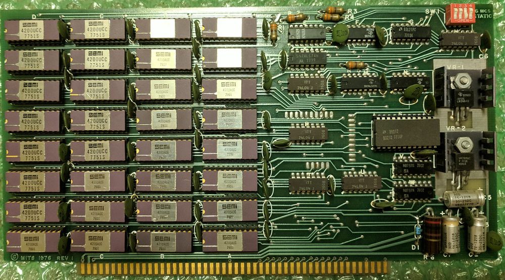
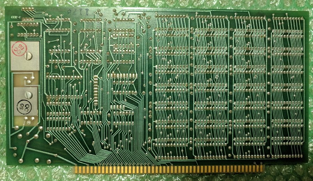
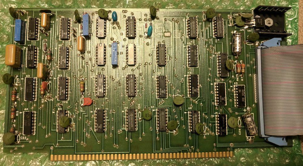
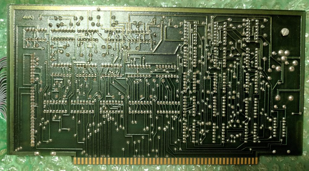
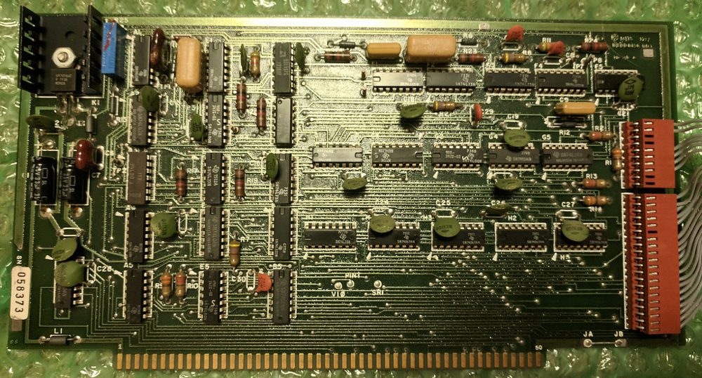
Public-domain advertisement scans exist for several more boards — the 88-2SIO with the 88-PIO in Byte's January 1976 issue, the 4K static board that April, the 88-80LP's control card in December 1975, and a labeled 16MCS in Kilobaud, January 1977 — and the ledger of what is licensed, what is not, and what was searched without result lives in the project's research notes. Nothing cleanly licensed has been found for the 88-ACR, the 88-VI, a labeled 88-PMC, the small memory boards or the 88-EC, which is why the cage stays drawn.
The switches were not silver
They are here, or they were until August 2026: every one of the twenty-five drawn with the same chrome gradient. The reference photograph shows a four-colour panel, and the colours are not decoration. Switches 15 down to 8 are magenta and 7 down to 0 are cream, and that is exactly the sense-switch boundary this page spends a chapter explaining. MITS printed the distinction on the hardware in colour, at the factory, and this page had been teaching it in prose while drawing it away.
The six real control switches are teal. The two AUX switches, which were never wired to anything, are the only black ones, so the panel tells you they are different before you read a word. The power switch matches the data half.
And the silver is real too, which is why the memory is a fair one. The coloured caps are moulded plastic, but the bushing and collar under each of them are bare nickel-plated metal, and there is a bright ring of it at the base of every switch on the panel. A photograph of the back of a real machine shows nothing but metal switch bodies. Both answers are right about different parts of the same switch.
Why the lamps blur, from the schematic
This is the part of the page most likely to be compared against a memory or a video, so it is worth saying exactly what the circuit does. On drawing 880-105, Computer Front Panel Display, each of the sixteen address lamps runs from its bus line through a single 220 ohm resistor to the lamp and on to ground. No latch, no buffer, no driver chip. Nothing is multiplexed: every lamp has its own resistor, thirty-six of them, R24 to R59, one per lamp. The data lamps are the one exception and only electrically: they hang from +5V down into a 74LS04 inverter that sinks the current, so the polarity is flipped on the way but a lit lamp still means a one.
Wired to the bus with nothing in between, a lamp shows whatever the bus is doing, two million times a second. It cannot do anything else. MITS said so themselves, in the operator's manual, immediately after explaining that a lit lamp means a one: “While running a program, however, LEDs may appear to give erroneous indications.” The blur is not an effect this page adds. It is the honest behaviour of a lamp soldered to a bus, and the manual warns you about it.
The eight status lamps are the ones that are different, and the difference is not on this board. Their signals come through an Intel 8212 latch on the processor board that catches the status byte at the start of every machine cycle and holds it for that cycle. So they step once per cycle where the address lamps run free. This page samples the bus once per access, which is once per machine cycle, so it already reproduces both.
Brightness has a number too. 220 ohms against a TTL high, with a period red LED, puts about 10 milliamps through each lamp, roughly half what the catalogue used for its ratings. Not blazing, not dim: readable at arm's length in a lit room, which is what an indicator had to be.
Even the moment of switch-on is specified. MITS's troubleshooting table for the successor machine, which is bus-level behaviour and so carries, says a memory board present at address zero shows the random pattern held by that board on the data lamps, because static RAM does not wake up blank; and with no board fitted at all, every data lamp lights, because nothing pulls the open bus low. That sentence sits on page 4-17, and it is the one quotation on this page nothing here can check: the bitsavers scan of the 8800b documentation is 195 pages and its section IV stops at page 4-15, while referring forward to a waveform on 4-30 that it also does not contain. Every page of it was searched. The claim is kept because the behaviour is independently true of static RAM and of an open bus, and the page says where to look rather than pretending the look succeeded. This page does both: flick the power switch and the RAM wakes scrambled, and a machine with its memory pulled wakes with the data row solid.
And lamp depth, the one dimension the successor machine specified at 13/16 of an inch, was on the original machine not specified at all: the assembly manual has the builder align each LED by eye against its dress-panel hole, then concedes: “Due to supply variations, the LED's in your kit may or may not fit all the way through the holes” (p.21). Every original panel's lamps sit at whatever depth that day's parts allowed, which is worth knowing before treating any photograph's lamp depth as a dimension.
The loader on this page, against the ones MITS printed
The walkthrough has you toggle in a sixteen-byte bootstrap loader written for this machine. MITS published three of their own, in Appendix A of the Altair BASIC Reference Manual, 1975. Theirs are twenty and twenty-one bytes, and they are the same shape as ours: ask the card whether a byte has arrived, take it, store it, move along. There is no checksum in any of them. This page said otherwise until August 2026 and was wrong.
They will not load this tape, though, and the reasons are about the machine rather than the loader. They talk to an 88-SIO at ports 000 and 001, where this page has an 88-2SIO at 020 and 021. And they fill memory downward from the top of an 8K Altair BASIC, stopping on a byte that matches a register, where the tape here is 1,920 bytes of Tiny BASIC that has to land at address zero. Ours is four bytes shorter because it needs no stopping condition: you stop it.
The nicest thing in that appendix is the stack pointer. MITS set it to 022, which is inside the loader itself, so every RC and RZ and RNZ "returns" to address 0003 and drops back into the polling loop. A return instruction used as a jump, to save a byte, in a program twenty bytes long.
Their procedure is also the one this page walks you through, down to the order: put the switches down, EXAMINE, set 041, DEPOSIT, then DEPOSIT NEXT for every byte after it. Their checking step is here too. Six of MITS's twenty-one steps have you examine the whole loader back, one address at a time, against what you meant, and the walkthrough keeps that step: it does the finding, then puts the offending address on the switches and leaves the fixing to you on the panel, which is where their step 11 leaves you anyway.
And there was a way out of the morning ritual. MITS's own software FAQ asks “When will the bootstrap loader be available on PROM?” and answers that the boards are available and that PROMs with the bootstrap on them cost $40. The answer is quoted in pieces because the scan's OCR renders the word bootstrap in the middle of it as “bootstxo.hJ”, and a quotation nothing can check is a quotation this page does not print. Fit the 88-PMC in the cage on the main page and the machine becomes that one: the sixteen bytes are simply there, burned in at 377 000, still there after the power goes off, and DEPOSIT cannot dent them.
How the PROM card finds itself on the bus
Three stages of decode. The top five address bits go to a DM8131 comparator against five switches, each settable true or complement, which is how one card straps to any 2K boundary in the 64K space. The next three bits drive a 74154 wired as a three-to-eight decoder that picks one of the eight 256-byte PROM sockets. The low eight go to every PROM in parallel, and the chip itself decodes the byte.
The read gate is the careful part. Board-select alone is not enough, because an I/O device can share the same bit pattern on the address lines, so the card enables its bus drivers only on board-select AND SMEMR — the status signal that says this cycle is a memory reference and not an I/O one. And that is the entire bus interface: eight tri-state drivers pointing at the bus. There is no write line anywhere on the schematic, which is why DEPOSIT into the window does nothing here. Nothing was left out; there was nothing to leave out.
Two details this page does not model, named so they are not mistaken for modelled: the card could insert zero to three wait states depending on PROM speed (a 1 µs 1702A wanted one), and it powered its PROMs up in pairs, switching VGG in under 30 nanoseconds, so only two chips drew current at a time. Both are electrically real and lamp-invisible.
MITS 88-PMC documentation, 1976 (reprinted April 1977): Theory of Operation pp.1–5, Memory Address Selection pp.25–27, schematic 8800-30 (drafted 16 Oct 75).
What a BASIC tape actually sounded like
Paper tape was not the only way in. Owners who bought the 88-ACR loaded BASIC off an ordinary cassette recorder, and the sound of it was two tones: 2400 Hz for a one, 1850 Hz for a zero, one tone per bit at 300 baud — a start bit, eight data bits and a stop bit, ten bit times a character — which works out to thirty characters a second and about a minute of warble for a Tiny-BASIC-sized tape. Between bytes and before the data starts, the line idles at a solid 2400. The manual even hands you the arithmetic: a good tape reads back near 2125 Hz on a frequency counter, which is the two tones' average.
This is not the Kansas City standard, and the proof is numeric rather than a MITS denial that does not exist: Kansas City encodes a zero as four cycles of 1200 Hz, where MITS uses 1850, and the ACR shipped before the November 1975 symposium that produced the standard. The mark tone coincides at 2400 Hz; the space tone gives it away.
Electrically the ACR is an 88-SIO B serial board with a modem board bolted to its back — the manual reprints the whole SIO manual inside itself — wired by the book to addresses 006 and 007, status and data. Jumpers could put it anywhere even-numbered; MITS's software expected 6 and 7, so that is where a machine that ran MITS's own software had it.
MITS 88-ACR documentation, 1975 (second printing Feb 1977): the assembly sections, the Modem Board Theory of Operation, and the alignment procedure.
The datasheet is a warning about brightness. The RL-21 was rated 0.7 millicandela at 20 milliamps, the panel gives it about ten, and light output tracks current, so each lit lamp made something near a third of a millicandela, where a garden-variety modern indicator is twenty to a hundred times brighter. And the lens is fully diffused, a 180° viewing angle with no beam and no hot spot. That is why the panel glows in period photographs instead of glaring, and it is the reason a lit lamp here is drawn as a soft bloom rather than a bright dot with a shine in the middle.
The RL-21 datasheet, line by line
Gallium arsenide phosphide in a red diffusive moulded lens. The plain RL-21 was rated 0.7 millicandela typical at 20 milliamps; its sibling the RL20 ran 1.2, and both could take 100 milliamps continuous. MITS bought the dimmer one, which fits a sixty-cent unit price. The page quotes no forward voltage because the datasheet gives none — its “3.0 V” column is peak inverse voltage, a reverse rating, and borrowing a VF from general knowledge would be dressing a guess as a citation.
The package: a 5.08 mm dome — exactly 0.200 in, the 5 mm envelope, though the page does not call it “T-1¾” because the sheet never does — on an 8.64 mm body, rectangular leads on 2.54 mm centres, short lead the cathode. The line that matters most for rendering is the sales pitch: a 180° viewing angle, which the sheet calls extremely suitable for panel use. No beam, no hot spot, the same apparent brightness from any seat in the room.
Restorers today fit an Everlight HLMP-D150A behind a 2 K resistor — about 1.6 milliamps, a sixth of the original's current, because a modern part is that much more efficient. Its 65° cone is nothing like the RL-21's 180°, which is why a replica panel does not read the same from off-axis as an original.
Litronix data page for the RL20 and RL21, 1975/76 databook scan, read as an image: the only copy reachable is behind a datasheet site's JavaScript, so nothing here can check its words against text and this page does not quote it; Altair 8800c Front Panel Manual (deramp.com), parts list, Sept 2024.
The Theory of Operation is where the rest of the panel's behaviour comes from, including the sentence that this page got wrong until August 2026 and now obeys: “The machine must be stopped for any of the front panel switches except RESET to be active.” A HLT stops the processor but does not hand the machine back, so the panel stays dead until you press STOP yourself. The successor machine's manual states the same rule in its switch table: “The RUN position allows the CPU to process data and disables all functions on the front panel except reset.” (Altair 8800b documentation, Table 2-1) — so it is a design rule of the family, not a quirk of one machine.
No MITS document names the typeface. Two people who went looking independently, one identifying type from a Computer History Museum specimen and one making reproduction panel artwork, both land on Helvetica for the switch and lamp labels, with the ALTAIR 8800 nameplate in Tuxedo. The machine photographed for the January 1975 Popular Electronics cover wore Microgramma instead — and that unit was the non-functional mock-up built after Railway Express lost the one prototype in shipping, so it is evidence about a photographic shell, not a shipped machine. Take the identifications as good ones rather than documented facts. The two-typeface split has a mechanical explanation the assembly manual supplies: the nameplate is not part of the dress panel's silkscreen at all but a separate adhesive plate, specified silver, stuck on “on the very bottom, beneath the Switches” after the case is assembled (p.77). Two typefaces because two parts, made in two different steps. The panel-maker adds one detail that is checkable and checked: MITS drew the numeral one as a bare vertical stroke, with no flag and no foot, which is what this page draws.
Where the panel's actual size comes from
There is no dimensioned drawing of the dress panel, and the assembly manual explains why: the panels arrived from MITS already drilled and already printed. The builder never laid anything out, so there was never a template to publish. That is a better answer than not finding one.
But the lamps are not positioned by the dress panel. They are positioned by the Display/Control board, because the LEDs mount to it and stick through. And the board's circuit artwork survives, which is a manufacturing document: exact by construction, with no lens and no perspective in it. Every layout of that era sits on a tenth-of-an-inch grid, so the chip footprints on the board are a ruler with known markings. Measuring two of them gives the scan's scale, and measuring the lamp footprints against that gives a lamp pitch of 0.6 inches, six grid units, to within eight tenths of one per cent.
That is one real length, and this page already had every ratio off the photograph. Together they give the panel's size without anybody's tape measure: 0.6 divided by the measured lamp pitch of 0.0365 makes the face 16.44 inches wide, and the measured aspect makes it 6.48 tall. An owner who put a tape across their own machine got 16.5 by 6.5, give or take an eighth. Both numbers land inside that.
Three sources, three different kinds of instrument, one answer. A photograph can be foreshortened, a tape can be off by an eighth, and a circuit board can be neither.
Still not found, after the MITS manuals, the schematics, bitsavers and the restorer forums: any authority on switch handle colour, which varies across surviving units. That one needs a photograph survey rather than a document search.
The other Altairs
This page models the original 8800 and nothing else, but the family's other members keep being offered as evidence about it, so here is what this notebook has verified about them and what it deliberately has not.
The 8800b of 1976 has a different kind of front panel entirely. The 8800's panel is gate logic soldered to the bus: EXAMINE is a circuit. The 8800b's panel is a small machine of its own. Its Display/Control board carries a PROM, and every switch operation is a microcoded routine that jams instructions at the processor — EXAMINE is eight PROM steps that jam a JMP and the switch bytes onto the CPU (8800b documentation, Table 3-2, “PROM Programs”, with the footnote “All PROM address and data information is octal”). Same words on the panel, different machine underneath, which is why no 8800b fact is allowed to migrate into this page's geometry or behaviour without being re-proven on 8800 paper. Two crossed over, carefully: the stopped-panel rule, which the 8800's own Theory of Operation states independently, and the b's 13/16 in panel-board standoff, recorded here only as MITS's later fix for the align-the-LEDs-by-eye step the 8800 assembly manual concedes.
The Altair 680, announced November 1975 and shipped the following May after design delays, is the Motorola 6800 sibling: different processor, different bus, no bearing on this page's emulation. Its BASIC was Altair BASIC converted to the Motorola 6800 by Ric Weiland after Paul Allen rewrote their processor simulator for the new chip — the same write-it-before-you-own-the-machine trick, performed twice.
The 8800a revision and the Turnkey model exist, and this notebook has not read their manuals, so nothing here rests on them. The Turnkey is the interesting absence: MITS's own answer to the question the tape walkthrough teaches — whether you need a front panel at all once a ROM can do the toggling. When its documentation gets a proper read it earns a section; until then it is a name on the shelf, not a source. The line itself ended quietly: after the 1977 sale, Pertec marketed the machine briefly as the PCC 8800 before retiring it.
The disk, and how it was checked
The 88-DCDD is three ports, and every bit of them is in MITS's Disk Operators Manual: select and status at 010, head control and the sector position at 011, data at 012. The status flags are true when they read zero. SIMH's AltairZ80 restates the same registers in its source, which is MIT-licensed, and the two agree bit for bit.
The difference is time. SIMH has no clock under its disk, so it stands one in: the sector register reports "sector true" on every other read and moves the counter on between them, which is enough for software that polls. Here the disk turns on the processor's cycle count. At 360 revolutions a minute a sector hole passes every 10,416⅔ cycles, and the manual's timings follow from where the disk is: the sector pulse lasts 30 microseconds, the first byte is ready 140 after it, one comes every 32, the head settles 40 milliseconds after it is loaded, and a step takes 10. A read loop that falls behind gets later bytes rather than an error. The 30 microsecond pulse is what makes the alternation unnecessary: a program polling every 24 cycles sees each one begin and end.
The software written for the hardware is the test. None of it was read while the timing was written, and all of it runs: MITS's own disk boot PROM, Disk Extended BASIC 4.1 and Altair DOS 1.0 of 1977, Burcon's CP/M 2.2 of 1980 reading and writing, and SIMH's CP/M disk. Their rights are unresolved, so the test fetches them from Peter Schorn's collection into a cache outside the repository, checks each against a pinned SHA-256, and ships none of it. Two deliberate breakages prove the test can fail: take the head current switch out of the BIOS and every inner-track write is flagged, 735 of them in the run of 18 September 2026; add four instructions to the read loop and the boot fails the way the hardware would, with the loader typing C for a checksum it cannot match.
MITS's boot PROM was measured rather than read. Traced on the emulated controller, it reads physical sectors 0, 2, 4 and so on of track 0, lays each one's 128 bytes of data end to end from address 0 until the length in the first sector's bytes 1 and 2 is loaded, then clears the controller and jumps to 0. This site's own loader keeps that contract, so MITS's PROM boots this site's disk and this site's PROM boots Burcon's. Like MITS's, it copies itself into RAM first: the 88-PMC's 1702A PROMs needed one to three wait states on every access, and a loop with 64 cycles to take each byte cannot spare them.
The format is the real disks'. On the first six tracks a sector holds its track number with the sync bit, two bytes of boot-file length, 128 bytes of data, a stop byte of 0FFH and a checksum of the data. Beyond them it holds the track, the sector as it was asked for, MITS's file number and byte count, a checksum that also counts those and a two-byte pointer, then the data, the stop byte and a zero, and MITS spread the sectors out by multiplying by 17 modulo 32. CP/M's layout on top of that, the block size, the directory and the skew table, is Burcon's, so the disks interchange. And every real image measured is 337,664 bytes where 77 tracks of 32 sectors of 137 bytes make 337,568: the last 96 are all 1AH, CP/M's end-of-file filler, because the images were CP/M files once and were rounded up to a whole 128-byte record. The disks made here are padded the same way, which is also the size SIMH looks for.
CP/M is DRI's, built from DRI's source. The assembler that builds Tiny BASIC learned DRI's dialect from the CP/M 2.2 manual, including a rule that is easy to miss: "!" ends a line even inside a comment, and DRI's command processor depends on it, because the line nosub: ;no submit file! call del$sub is a label, a comment and a CALL. Built that way the CCP and BDOS equal the system inside DRI's shipped MOVCPM.COM in all 5,632 bytes but six, the serial number DRI stamped into each copy, and assembling twice 100H apart finds the 1,073 bytes that are addresses, which is MOVCPM's own relocation bitmap bit for bit. The same assembler once let an EQU named WRITE, the controller's write-enable bit, silently replace the BIOS routine of the same name, so the BIOS's jump table jumped to 0080H. It refuses a name defined twice now.
Three sources of DRI's utilities disagree. The Unofficial CP/M Web Site's copies of LOAD, STAT and SUBMIT stop short of a whole record; every byte they have matches the copies on Burcon's 1980 disk, whose tails are what SAVE leaves after a program. Its ED is unpatched, and the 1980 disk's is CP/M 1.4's. The ED on this disk is the one carrying DRI's own ED20PAT.ASM, checked by assembling that patch and finding it in place byte for byte. The full account is in src/cpm22/README.md.
A third implementation agrees. SIMH's AltairZ80, built from source on 18 September 2026, boots the disk this page saves with its own boot ROM, and ASM, LOAD and the resulting HELLO run on it.
Interrupts, found by the software that uses them. Altair DOS asks "INTERRUPTS?" when it starts. Answered yes, it writes 207 to the 88-VI/RTC's port, sets the 2SIO's control register to 221 (receive interrupt on), and points RST 7 and RST 2 at its keystroke handler. The 2SIO's schematic jumpers the board's interrupt to any vectored level or to PINT, and SIMH's keyboard interrupt goes to 0038H, which is RST 7: PINT, answered by 377 off the open bus. So the page straps the 2SIO there, and the disk controller too: its interrupt, once a sector with IE set and the head settled, is cleared by any interrupt acknowledge cycle, as the FDC+ manual records of the original. With that, Altair DOS runs with interrupts on, with or without the 88-VI in the cage, and every keystroke after the answer arrives through RST 7.
The assembly examples, and how they were checked
Written to DRI's agreement, and nothing else. The four programs in the chapter Talk to CP/M, FIB, REVERSE, SHOW and NOTE, use only what section 5 of the CP/M 2.2 manual promises: load at 0100H, call 0005H with a function number in C, find the typed file name at 005CH and the buffer at 0080H, and jump to 0000H to finish. The proof that they depend on nothing else is that this disk's FIB.COM runs unchanged under Burcon's CP/M of 1980, whose BIOS has none of this site's code in it.
Two assemblers, one set of bytes. Each program was assembled by DRI's ASM and LOAD under CP/M on the emulated machine, and the tests do it again and compare every byte. The repository's own assembler, the one that builds Tiny BASIC, assembles the same sources, and its bytes must equal DRI's over the whole program. The first time they were compared they did not: a label called TITLE is reserved in DRI's ASM, which marked the line with an N, dropped it, and moved every address after it, while the repository's assembler took it without complaint. The build had missed the error too, because it looked for a space after ASM's error letter and ASM runs the letter into the address. Both are fixed: the label is renamed, and the build stops on any line ASM marks.
Why they end with a jump to 0. The first versions saved CP/M's stack pointer, used a stack of their own, and returned to CP/M's at the end, as DRI's DUMP.ASM does. That works from the command line and fails under DDT, which starts a program with the stack pointer at 0100H and nothing on it to return to: FIB ran its numbers and then ran off into memory until DDT caught a breakpoint instruction at C1A3H. A warm start, a jump to 0, works under both, and it is how most CP/M programs of the period ended.
Each output is checked against something other than itself. FIB's numbers are worked out a second way and laid out as the program lays them out; REVERSE's lines are reversed a second way; NOTE's file is read back by SHOW, by CP/M's own TYPE and by the repository's Python disk reader, which finds the lines followed by 1AH to the end of the record. The DDT session the chapter prints is typed in full, command by command.
The C disk, and how it was checked
What is on it, and why it may be. Leor Zolman's BDS C 1.60, from the distribution he published when he released all of it into the public domain on 20 September 2002: the compiler in its two passes, CLINK, the run-time package and the function library, each file byte-identical to the archive's, with the hashes pinned in the tests. Scott Layson's L2 linker, whose source says it is public domain. David Kirkland's CDB debugger, part of the same package. This page's own CP/M underneath, and five programs written for it.
The debugger had to be unpacked on the wrong processor. CDB ships inside CDEBUG.LBR, compressed with CRUNCH, and the package's own UNCRUNCH.COM stops with a message that it needs a Z80. This machine is an 8080. So it was run once in SIMH's AltairZ80, built from source, with the processor set to a Z80. CRUNCH checks each file as it decodes, and every member came out clean. The proof that matters is that the result works: a program compiled with -K and linked by L2 is debugged in CDB on this page's 8080, and the tests type the whole session the C chapter prints.
Built on the machine, and built again. L2 and every example were compiled and linked by BDS C running under CP/M on the emulated Altair, not by a compiler on a modern computer, so the disk carries what a 1979 owner would have made. The tests build them all again the same way, about eleven seconds with the emulator running flat out, and compare every byte. The HELLO.COM a visitor makes by typing CC HELLO and CLINK HELLO is the one on the disk.
Each example is checked against something other than itself. SIEVE's 1899 primes are counted a second way, by trial division, and match the figure Gilbreath's BYTE article gives. MANDEL's drawing is compared character by character with a second implementation of the same sums in JavaScript, which divides the way C does and fails if any value would not fit in 16 bits; the largest square it needs is 65,025, under the 65,536 that 16 bits allow. GUESS is played to a win by halving the range. The claim that HELLO prints a character at a time is counted at address 5: fourteen calls to function 2 and fourteen to function 11, and nothing else.
What this covers, and what it leaves out
A reader in September 2026 put the gap plainly: this is not a complete emulation of every Altair configuration. That is true, it is on the main page in the table above, and it is a decision rather than a shortfall. The three things people name are worth answering one at a time.
The disk was the one with a case, and it is built now. A machine with an 88-DCDD boots an operating system and stops needing the panel, which is the end of the front panel's own story, so it was the one missing part that changed what a visitor can do. It got its own chapter on the main page, and the section above is how it was checked. The other two are still refused, for the reasons below.
The 8800b is a different machine wearing the same words. The section above says why, and that rule is what keeps this notebook honest: its panel is a microcoded board, and a fact proven on its paper is not a fact about the machine you are using.
Nobody simulates the S-100 bus at signal level, and nothing you could run would know. Bus timing matters when period boards from other manufacturers have to work together in one cage, which is a hardware compatibility question rather than something a program can observe.
The general point is that completeness is not one finish line. MAME, whose stated goal is documenting hardware as faithfully as possible, ships an Altair driver that models the 1977 Turnkey rather than the 8800 or the 8800b, has no disk code in it, and is marked as not working (read from src/mame/mits/altair.cpp, 18 September 2026). The most accuracy-driven emulation project in existence covers less of this machine than this page does, and says so.
The projects worth comparing are each complete in a different direction. SIMH's AltairZ80 covers the most hardware: the minidisk, the hard disk, other processors and boards this page does not have. z80pack simulates the Altair among many other CP/M machines. The Altair Clone is the machine itself, in metal. What this page covers is the arc: a program toggled in by hand, BASIC loaded from tape, then the same machine booting CP/M off a floppy, assembling a program on it and compiling C, each step explained on the main page and checked here against MITS's paper, the period software and a second emulator. For more hardware, go to those three, all linked from the main page. For the way the Altair went from switches to an operating system, this page walks the whole of it.
The documents, in one place
Every scan this site leans on, and what each one settles. The main page's source list is the short version; this is the whole shelf, and a build test holds the two together so neither can drift.
MITS's own paper
- MITS Altair 8800 Assembly Manual — the archive.org copy with an OCR text layer, so the switch counts and the panel layout can be read rather than looked at. The OCR is partial: it is missing the addressing pages entirely, which is why the 1K-board quotation elsewhere on this site is still owed rather than confirmed.
- Theory of Operation & Schematics, the searchable scan rather than the image-only one beside it, which yields twenty-six bytes of text and OCRs its own title as “AGTAIR 8800 OO TTEORY Of OFEEATTON” — EXAMINE and DEPOSIT as circuits, the RUN/STOP flip-flop, and drawing 880-105 with the lamp resistors R24–R59. The stopped-panel rule is p.5.
- The Dunfield archive — Operator's Manual (the “erroneous indications” line, p.31), Assembly Manual (LED alignment by eye p.21, the adhesive nameplate p.77), and the parts and price lists the cage chapter is checked against.
- Intel Component Data Catalog, 1978 — the 8214 priority interrupt control unit as text: eight priority levels, a current status register, and a comparator that interrupts only above the level being served.
- MITS price list, 1 April 1975, and the same list as OCR text — the bitsavers scan with an OCR text layer, so the prices can be read rather than looked at. “8800 Altair 8800 Computer S 439 00 S 621.00”.
- Operator's Manual, part 3 — switch and lamp semantics, one control at a time.
- Altair BASIC Reference Manual — the three bootstrap loaders and the EXAMINE-back checking procedure of Appendix A; Appendix I's checksum-free cassette format.
- Altair 8800b documentation, May 1977 — the successor machine, and the source of every 8800b sentence quoted above: Table 2-1 on what RUN disables, Table 3-2 and its octal footnote, and the PROM-driven switch routines.
- MITS Software Information Package — the software FAQ, question 24, on when the bootstrap would be available on PROM.
- bitsavers, MITS 8800 — the bus definition and the card manuals for the 88-2SIO, 88-PMC and 88-ACR. The 88-VI/RTC manual lives on deramp.com and classiccmp.
- Scott Wilcox's memory check — an Applications Exchange column in INTERFACE, January 1976: a hobbyist's answer to the new-4K-board question (“memory chips do have a small failure rate”). Every bit pattern through every cell, the bad address and the pattern it failed on parked at 054–056. For a few hours on 2026-08-05 this index called it “the diagnostic MITS shipped”; reading the scan corrected that — it is a member's program from a club magazine, the archive's own label is “a published memory test program”, and no MITS-shipped diagnostic has been established here. The page's own memory test credits him now. Rights: a 1976 magazine column, status unchecked.
Component data
- Litronix RL20/RL21 databook page — the only located source for the lamp's 0.7 mcd rating and 180° viewing angle. Read as a scan, and that matters: the page behind that link is 226 kB of JavaScript with no PDF in its markup, so the two databook sentences quoted above are this page's own reading of an image and nothing here can check them against text. bitsavers holds only the 1982 Litronix catalogue, seven years late and without RL-21 in it.
- Fonts In Use, MITS Altair — the Helvetica identification, from a Computer History Museum specimen.
Listings and software
- Dompier's music — as published in the People's Computer Company newsletter, May 1975.
- Kill the Bit — Dean McDaniel's original listing, 15 May 1975.
- 8080 CPU diagnostics — the four-test suite the processor here passes, CRC-checked.
- Palo Alto Tiny BASIC 2.0 — Li-Chen Wang, in Roger Rauskolb's Intel-mnemonic translation, 1976. The interpreter this page runs.
The disk and CP/M
- MITS Disk Operators Manual, 88-DCDD — the preliminary release, scanned by deramp.com: the three ports, every status and control bit, and the timings the controller here is built on.
- SIMH, altairz80_dsk.c — Peter Schorn's MIT-licensed controller, whose header restates the registers, and whose change log records the two sector-register bugs it fixed in 2014.
- DRI, CP/M 2.2 Alteration Guide, 1979 — the seventeen BIOS entry points and the disk parameter tables this site's BIOS is written against.
- CP/M 2.2 manual, section 3 — DRI's assembler: its operator precedence, its IF, and "!" as the end of a line.
- The Unofficial CP/M Web Site — DRI's CP/M 2.2 source, and the 2022 grant from Bryan Sparks of DRDOS, Inc.
- Mike Douglas's reconstruction of Burcon's CP/M BIOS — where the disk format, the disk parameters and the skew table were read, and checked against the real disks.
- Peter Schorn's Altair software — MITS's boot PROM, Disk BASIC, Altair DOS and Burcon's CP/M, the software the controller's tests run.
- FDC+ manual — which of MITS's boot PROMs is which: DBL for the eight-inch drive at FF00, the Multi-Boot Loader for tape and cassette.
- Z80-Retro, cpm-2.2 — the copy of ED 2.0 with DRI's patch applied.
The assembly examples
- CP/M 2.2 manual, section 5 — “CP/M 2 System Interface”: the thirty-nine BDOS functions, and the addresses a program is written to, 0000H, 0005H, 005CH, 0080H and 0100H.
The C disk
- BD Software, BDS C — Leor Zolman's own page: first sold August 1979, released into the public domain 20 September 2002, and the distribution the C disk is built from.
- BYTE, September 1981 — Jim Gilbreath, “A High-Level Language Benchmark”, the sieve SIEVE.C runs, and its answer: “1899 is correct”.
- mojozork — not used; the smallest openly licensed Z-machine found, and the reason this page does not offer a one-click Zork: no interpreter for the 8080 exists under an open licence.
The history chapter's spine
- MITS company history — the collected account, with its footnote trail into Forrest Mims's and Les Solomon's own tellings.
- S-100 bus history — the cage chapter's sidebar: the connector that became IEEE 696.
- Reimer, “Total share”, 2005 — where the 25,000-units estimate comes from.
- RR Auction, lot 7011 — serial 222514K, sold $3,328; the FAQ's price and serial data point.
- Computer History Museum catalog 102626725 and Smithsonian NMAH object 334396 — where to stand in front of one.
The company this page keeps
A browser Altair is not a new idea, and pretending otherwise would be the kind of claim the rest of this notebook exists to prevent. The lineage, and what each project does that this one does not: SIMH's AltairZ80 emulated the disk system and ran CP/M long before this page did, and it boots the disk this page saves. Peter Schorn's browser simulator has run Microsoft's Altair BASIC on the web for years. David Hansel's Arduino simulator is the software inside the Altair-Duino replica kits. Rich Cini's Altair32 documented the Windows-emulator generation (its site comes and goes; no link that will last). wixette's 8800-simulator draws the panel logic in a page of JavaScript. What this page adds to that company is the measured panel, the duty-cycle lamps, and the teaching arc — and where it is behind any of them, that is recorded here rather than rounded away.
Sources for every claim above are on the main page's source list, and the machine itself is one click up. If you find a document this notebook needs, the address on the FAQ reaches a person.